 |
||||||
| Optics Cuvette | ||||||
| Optics Chamber | ||||||
| Sorting Switch | ||||||
| Assembly | ||||||
| Electronics | ||||||
| System Timing | ||||||
| Computer Display | ||||||
| Parts List | ||||||
| Contacts | ||||||
Embryo Sorter Website Eileen Furlong, David Profitt, Matthew Scott |
Electronics
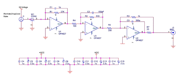
Two methods of measuring light intensity are used in this design. The first, a photo diode, is used to measure relatively high levels of light. This wavelength is primarily at the excitation wavelength, and is used to detect embryos as they pass through the detection optics. While this signal intensity may vary from embryo to embryo, the information contained in its amplitude is of little significance. This signal is amplified at a fixed gain. The other method of measuring light intensity uses photomultiplier tubes (PMTs). The sensitivity of a PMT is directly proportional to the voltage applied to its cathode. Therefore, the gain of these signals is adjusted by varying this voltage. Both detectors use a current to voltage conversion circuit similar to the one shown below.
PMT Preamp Diagram
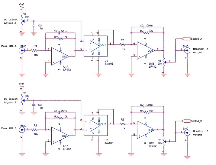
Signal scaling for both the PMTs and the photo diode are achieved through attenuation. This is easily accomplished using a potentiometer as a voltage divider. This approach has two advantages. First, the relative signal amplitude is directly proportional to the position of the panel indicator or knob. If one uses a multi-turn potentiometer and a counting dial, this value is directly readable. Secondly, because the gain of each amplifier is fixed, and because the frequency characteristics of an amplifier are related to its gain, overall system linearity and reproducibility are improved.
As in many optical measuring systems, there are several sources of DC errors in the output signals. The primary sources are unwanted light reaching the detectors, and leakage current from the detectors themselves. In the case of PMTs, this leakage current error can vary significantly with tube voltage. To compensate for these errors, a DC offset adjustment is included in the circuit - see diagram below.
Offset and Gain Diagram
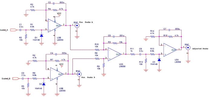
In this embryo sorting system, the signal from one of the PMTs is used to detect a very narrow band of light that represents fluorescence from a known source. However, light from other sources (autofluorescence) may also be present at these wavelengths, and may be detected by the PMT. To compensate for this, light is measured at wavelengths close to those of the known source, and is used to represent the relative intensity of the autofluorescence. A percentage of this autofloursence signal is then subtracted from the fluorescence signal. By proper scaling of these signals, a more accurate representation of fluorescence from the known source are obtained. The diagram below illustrates a simple circuit that accomplishes this. This circuit also AC couples the signals to eliminate any residual DC offsets.
Peak Detector and Gain Diagram
Since the objective of this device is to sort embryos based on the presence or absence of the fluorescence signal, some means of determining the position of the embryo is necessary. This is accomplished by determining the peak intensity of the photo diode signal as the embryo passes through the optics. The photo diode signal is used because its amplitude is relatively constant, and is less affected by the presence or absence of fluorescence. Once photo diode detects a peak, the magnitude of the adjusted fluorescence signal from the PMTs is compared to that of a threshold signal. If the system is set to save embryos that emit fluorescence, and this signal is greater than the threshold signal, two signals are sent: a new embryo (New) signal and a save embryo (Save) signal. Conversely, if the system is set to save embryos that do not emit fluorescence and this signal is greater than the threshold signal, only the New signal is output.
A dedicated microcontroller is used to produce the New and Save signals. The controller continuously measures the diode signal at 40 micro-second intervals. When the controller determines that the signal is negative it measures the fluorescence signal and then the threshold signal. At this time it reads the save above/below threshold input and generates the appropriate outputs. This cycle is repeated continuously as long as power is applied to the controller. It should be noted that the fluorescence signal is measured about 40 micro-seconds after the peak has passed, and that the outputs are generated at least 80 micro-seconds later. Using a microcontroller with an eight-bit analog to digital converter limits the measurement resolution to ~ 20 mV, assuming a maximum signal of 5 V. Thus, the signal must be at least 20 mV below its peak before the controller recognizes it. Our system uses a PIC16F84 microcontroller, Microchip Technologies, with an internal 8-bit analog to digital converter, operating at 5 V.