This aims to extend the work by Bennett, Mansure and Kaufman, etc in the 1950s. They considered the effect of various uplift gradients on behavior of levees in the Mississippi. For various reasons the situatation in California is a little different as we will demonstrate.
The animation intends to show how the response in terms of toe stability lags the rise of river level. This is a function of the capacitance of the system (water needed to saturate and raise pressures in the system, depends on k and capacity ). Eventually a weakened or liquified zone develops beneath the toe.
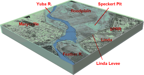
General condition at Linda

Effect of blockage of seepage at toe
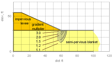
With upward seepage from an underlying pervious stratum and an assumed impervious levee (or building foundation) the gradient is amplified due to the concentration of flow at the toe. This can be demonstrated by flow net or finite difference analysis of seepage at the toe area. The average gradient away from the toe will be amplified by some multiplier as indicated below in the figure.

Example
total unit wt soil=110 pcf
critical gradient (full bouyancy)=
(110-62.4)/62.4=.76
assumed artesian head above toe=12
ft
blanket thickness=30 ft
upward gradient=12/30=0.4
ratio critical to average gradient=0.76/0.4=1.9
from the figure the gradient will exceed the critical (i.e. >1.9)in the toe area to a depth of about five feet. Foundation soil will be totally liquefied in this zone. Heavy boiling followed by bearing capacity failure of the lower few feet of toe would occur. Disturbance of the low density soil would result in propogation of the weakened zone.
All of this can be analyzed in
a system of linked applets; start with a (1) finite difference model of
the river, blanket, levee etc showing response over time of pressure beneath
the levee. A second model (2) shows development of pore pressure beneath
the toe. Finally a linked stability model (3)(wedge, Modified Bishop, etc)
demonstrates the development of instability. The sample applet below
combines (2) and (3) and computes the depth of an unstable wedge beneath
the levee toe for various assumed conditions. The presentation is quite
simple, but the computation involves 5000 smoothing repetitions of a finite
difference model (1 ft grid) of foundation pore pressures followed by progressive
searching of wedges to yield the depth of instability.