EE281 Final Project
“A Programmable Remote Control”
Gregory Larchev
December 12, 2001
Overview.
Programmable Remote Control (PRC) is a device, which can accept and store signals from a standard remote control, and play them back when desired. PRC is designed to work with any regular remote-controlled device, which uses infrared signals to transmit information. PRC reads signals through an IR-sensor and transmits them by the means of an infrared LED. At the heart of the device is the ATMEL Atmega163 microcontroller, which stores, processes and transmits the infrared signals in digital form and handles all the control routines. There are 4 control buttons: reset, record, play and switch. The device also has an LCD, which displays the number of the currently active memory cell, as well as its status (empty or not). When a user wishes to record a new signal, they would press ‘record’ button. A message would then appear on the LCD, and a ‘waiting-for-signal’ LED would light up. After the first infrared signal is received, the LED would turn off. After the device finishes recording the complete sequence, ‘DONE’ message would appear on the LCD. To play the signal back, user would simply push the ‘play’ button. The ‘switch’ button switches between different memory cells (each cell holds one recorded signal.) Currently the device can hold up to 4 signals. PRC is powered by 6 1.5V AA batteries; it also has an input power jack, which makes it possible to power PRC through a 5V ‘brick’ AC adapter.
Hardware.
PRC has relatively little external
hardware (by external I mean anything beyond the actual microcontroller), which
makes for a reasonably compact design. (This feature has also allowed me to
finish the project by the deadline.) The only major hardware parts are the
microcontroller, the IR receiver, the IR LED, the LCD, the power pack
(batteries and the voltage regulator), and various associated control hardware
(switches, LEDs, etc.) All the components have been soldered or securely
connected to a single board. Work is in progress to create some sort of an
external casing for the device, which would give it a more finished look.
IR receiver.
For my IR receiver I used a GP1U52X
infrared detector module from RadioShack. This module has 3 pins: power, ground
and signal. The ‘signal’ pin is usually ‘high’; when an appropriate infrared
signal is detected, it makes a transition to ‘low’. The module already
incorporates a bandpass filter, which is designed to only pass the signals in
the 40KHz range (a standard operating frequency for most remote controls). The
module also contains a demodulator, which eliminates the 40KHz carrier signal.
While it was designed to reject noise signals, the detector module is not
perfect: occasionally it would pick up noise, especially when used indoors
where fluorescent lighting is present. Therefore, the module should be isolated
from visible light in the room (enclosed in a box) when infrared signals from a
remote control are being recorded.
The datasheet for the decoder module
is available here.
IR transmitter.
The IR transmitter is simply an
infrared LED. Mine was purchased at RadioShack, but these devices are fairly
ubiquitous. Below is a connection diagram for the transmitter.

Please note that in my actual project
I have included a visible LED (not shown here) in series with my IR LED, just
so that it would be easier to tell when the transmitter is working.
LCD.
For my display I have used a standard
14pin 20x2 character display with a Hitachi HD44780 controller. To see how it
was interfaced with the Atmega163 ports, please refer to the Microcontroller
section of this document.
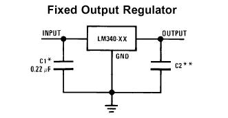
Power pack.
To power my device, I have used 6 1.5V
AA batteries (for a total of 9V), as well as a voltage regulator from National
Semiconductor (part #LM340S). This particular regulator has an output voltage
of 5V with an input voltage of 7V or higher. Below is a basic connection
diagram off of the manufacturer’s web site, that was used in my project:
For more information about the voltage
regulator, please go here.
The PRC also has an input connector,
which is compatible with most ‘brick’ type power adapters. The connector is
hooked directly to the board’s 5V power line (thus enabling the board to be
powered directly from the adapter.) This feature was originally incorporated to
make it possible to replace the batteries without having to turn the device
off.
Microcontroller.
I have used the ATMEL Atmega163
microcontroller. To clock it, an external 8MHz oscillator was used. One of the
improvements to my project would be replacing this oscillator with a slower one
(4MHz, 2MHz or 1MHz, for example), in order to conserve power. I was unable to
get my project to work with an internal 1MHz oscillator, perhaps because it was
not accurate enough for my needs. All of the microcontroller programming was
done through an STK 500 board; however, the PRC incorporates a serial
connection port which would allow the microcontroller to be programmed by using
the PonyProg® software package (the actual serial port connection diagram is
available here.)
The actual code will be described in the Software section of this document.
Below is a list of Atmega163 ports and pins that I have used.
Port
A: not used
Port
B:
Pin
0-7: LCD pins DB0-DB7 (respectively)
Port
C:
Pin
0-1,6-7: not used
Pin
2: LCD pin E
Pin
3: LCD pin R/W
Pin
4: LCD pin RS
Pin
5: LCD pin VLCD
Port
D:
Pin
0: ‘record’ button input (active low)
Pin
1: ‘play’ button input (active low)
Pin
2: IR detector input (active low)
Pin
3: ‘waiting-for-signal’ LED output
Pin
4: IR emitter enable output
Pin
5: ‘switch’ button input (active low)
Pin
6-7: not used
Accessories.
The only other hardware in my project that is worth mentioning is LEDs and button switches. All the LEDs are connected in a manner similar to the IR LED (see diagram earlier in the document). For button switches, I have used a circuit, which is similar to that on the STK 500 board:

The
only difference in my circuit was the 130 Ohm resistors used in place of 150
Ohm resistors.
Software.
Most of the functionality of the PRC was implemented in software. Described below are major building blocks of the code.
Signal recording.
The main function contains an
infinite loop, which continuously monitors the user-controlled buttons. If the
‘record’ button has been pressed, the program begins to execute a recording
subroutine. This subroutine waits for the first signal from the IR detector.
After the signal has been received, the subroutine starts a timer (Timer 1),
which goes on to count until a new transition is registered on the IR detector
input. When the new transition is registered, the timer value is stored and the
timer is cleared. This cycle continues for 75 transitions. The subroutine
effectively records the number of timer ticks between the IR detector
transitions. Most remote control devices transmit their signals as 16-bit packets,
which would translate into 32 transitions per packet (or slightly more, depending
on the encoding scheme.) Initially, I was only recording 50 transitions; such
scheme, however, has precluded some of my remote functions from working. I
concluded that some remote controls (mine included) probably need 2 16-bit
packets to transmit information; hence, the number of recorded transition
intervals was increased to 75. The word ‘Recording’ appears on LCD when the
recording subroutine is started, and a ‘waiting-for-signal’ LED light turns on.
The LED light turns off after the first transition is received; the word
‘Recording’ gets replaced by the word ‘DONE’ when all 75 transitions have been
recorded (at which point the subroutine exits.)
Signal storage.
The PRC can currently store up to 4
remote control signals. The signals are stored in an array of 75 entries long,
each entry being 16 bits (a short.) Hence, the on-chip RAM is providing all the
storage space necessary. Future plans include amending the project with some
sort of non-volatile external storage device (such as a memory card), so that
more entries could be stored, and they would be preserved even when power is
turned off. The program also stores 1 bit for each storage cell, which tells us
whether a cell is empty or has been written to.
Signal transmission.
When the ‘play’ button is pushed, the program
goes into the transmission subroutine, which transmits the currently indexed
message (‘switch’ button is used to pre-select the message.) The main transmission
challenge is that a transmitted signal has to ‘ride’ a 40KHz carrier wave. The
40KHz signal is generated entirely in software. The subroutine looks at each
entry in the stored array of timer delays, and runs the same timer until it is
equal to the current entry, then switches between transmitting ‘high’ and ‘low’
(the first entry is always transmitted as ‘high’, and each subsequent one is
the inverse of the previous one.) To transmit ‘low’, subroutine simply grounds
the IR emitter output pin (which goes to the base of the transistor controlling
the IR LED.) To transmit ‘high’, the subroutine enables a special global
variable emitVal. The program also has an interrupt routine running, which
generates an interrupt every 12.5us (via Timer 2.) When the interrupt is
generated, the handling subroutine checks to see if emitVal is enabled. If it
is, the interrupt routine toggles the IR emitter enable pin on each call, thereby
producing a 40KHz carrier signal. The transmission subroutine exits after
completing 75 transitions.
LCD
control.
The LCD control subroutines are practically identical to those used in Lab #3. In order to make it easier to display text, I wrote an lcdPrintString function, which prints a string starting at the specified LCD address. One important thing I have discovered when running my program is that interrupts should be turned off when the LCD is being written to; otherwise, the LCD might receive incorrect information.
A copy of my complete code can be found here.
Potential improvements.
There are a few things that could be added to my project to make it more functional. Here are some ideas:
- An external casing, to make PRC look more like a finished product.
- A low-battery indicator.
- An external non-volatile memory pack, to increase the number of messages that can be stored.
- A feature, which would allow users to name various stored signals to better distinguish them from one another (this feature would probably require additional external input device, such as keyboard or keypad.)
- Replacing the 8MHz oscillator with a slower one to improve power consumption.
Links.
- National Semiconductor website.
- Click here to see what other research is going on in the field!