EE281 Final
Project Self-Balancing
Robot Geoffrey Bainbridge
Dec
12, 2001
Introduction
The goal of
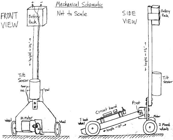
this project was to build a one-legged robot which balances itself. The robot has a vertical shaft with two
wheels at the bottom. There is also a
“tail” with a third wheel at the end, but this tail is attached through a pivot
point, so the third wheel does not help to balance the robot. The robot can fall forwards or backwards,
but not to the side. It senses its tilt
and drives forwards or backwards to compensate.
Feedback
control is provided by an ATmega163 microcontroller. It digitizes the voltage from a tilt sensor on the vertical
shaft, and uses this information to control the driving voltage of a DC motor
attached to the two front wheels. The
microcontroller is programmable through a serial port, to allow for
modifications to the robot or refinements of the control scheme.
Mechanics
Tilt is
equivalent to sideways gravitational force.
The main difficulty in the control scheme is distinguishing tilt from
horizontal acceleration. If the tilt
sensor was mounted at the center of mass of the vertical shaft, then it would
be impossible to measure tilt dynamically, because if the robot was tipping
over due to gravity, the tilt sensor would be in free fall and register no
force at all. However with the battery
pack at the top of the shaft and the tilt sensor near the bottom, the
horizontal acceleration due to gravity is reduced, and the sensor is able to
detect tilt. Unfortunately, location at
the bottom of the shaft makes the tilt sensor sensitive to horizontal
acceleration from the motor. This
unwanted feedback can be mitigated to some extent in processing, but not
eliminated, as we shall see later.
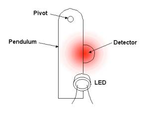
The tilt
sensor uses an LED and CdS photoresistor to measure the motion of a small strip
of metal hanging from a pivot point at the top, as shown below. When the machine tilts, the strip moves to
cover either more or less of the detector, producing an approximately
proportional change in resistance. The CdS photoresistor is in series with a
larger fixed resistor, so the current through it is approximately constant, and
the change in resistance produces an approximately proportional change in the
voltage across it. This voltage is used
as the output signal.
Tilt Sensor
The metal
strip is about ¾” long and has a resonant frequency of 4.8 Hz. The sensor response peaks sharply at this
frequency and then rolls off at 20 dB/decade above. Attempts to compensate for the sensor response are discussed
later, under the heading of Feedback Control.
The motor is
a small DC motor weighing about 1 ounce, and is rated for 3-6 V, but will
operate over a wider range. The drive
assembly was designed for low friction, and will turn (under no load) with only
0.4 V applied voltage, drawing about 10 mA, for 4 mW power consumption. The power is supplied by two 9V batteries in
series, which can produce a maximum of 500 mA, for a peak power of 9 W. The small mass and low friction of the motor
help to make it respond rapidly and linearly to the driving voltage. However the total mass of the lower part of
the machine is about 5 ounces, which creates a significant inertial load.
The robot
was originally intended to be just a vertical shaft with two wheels, but the
tail was added to keep it from twisting around the vertical axis. Any bump or vibration can cause it to lean
to one side, which will lift one of the drive wheels off the ground. With only one wheel touching, it tends to
spin around and become uncontrollable.
The tail prevents this from happening.
Electronics
The circuit
is built around an ATmega163 microcontroller.
128 times per second it samples the voltage from the tilt sensor and
generates an appropriate value for the motor torque to correct the tilt. The motor drive signal comes out on two
pins. OC1A is a pulse-width-modulated
signal which controls the magnitude of the drive voltage. PC2 is binary hi/lo signal which indicates
the direction. These control signals go
to an LMD18200 motor driver chip, which switches power from a separate 18V
supply into the motor.
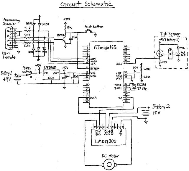
The system uses 3 batteries and 3 different
supply voltages. Two batteries provide
unregulated 18V for the motor, and the third battery provides regulated 5V for
the microcontroller and unregulated 9V for the tilt sensor. 9V is used for the tilt sensor, since a
higher supply voltage allows us to put a larger fixed resistor in series with
the photoresistor, and get a wider range of linear voltage output from the tilt
sensor than would be allowed by a 5V supply.
The 9V supply is not regulated, since the sensor operates over a wide
voltage range and is automatically calibrated by the microcontroller (see
description of integral center adjustment under Feedback Control). The motor supply does not need to be
regulated either, but it needs to be separate, so that the large switching
currents do not feed back to the tilt sensor input.
The circuit includes a serial port programming
interface to allow for software changes.
Software
The control program was written in C (rather
than assembly language) because the program requires math functions not
directly supported in AVR assembler (such as division), and speed is not much
of an issue. Since we sample 128 times
per second, and the processor runs at 1MHz, there are about 8k cycles available
to compute the output before the next input comes in.
The main program initializes the system and then
goes into an endless wait loop. After
that everything happens on the Timer2 overflow interrupt. Timer2 runs off an external 32k crystal,
since the timing of the microcontroller’s internal LC oscillator is not very
reliable. Its nominal clock rate is 1
MHz, but I measured it actually running at 790 kHz. Good timing is required for the matched filter part of the signal
processing (see next section). If the
sample rate is off, the filter will not be matched to the system response.
Other than that, the software architecture is
straightforward, just a linear sequence of commands. For details see the code listing (with comments) at the end of
this report.
Feedback Control
The system uses proportional-integral-derivative
(PID) control. The most basic part is
the proportional response. When the
sensor measures a tilt, a proportional voltage is applied to the motor, in the
appropriate direction so as to correct the tilt and balance the machine. The larger the constant of proportionality,
the stronger the correction will be.
However this does not necessarily mean that the system will be more
stable, since there is a phase shift between the sensor measurement and the
response of the mechanical system.
With a simple, uncompensated proportional
response, the system oscillates at the sensor resonance frequency of 4.8
Hz. This oscillation arises
spontaneously and grows to the point where it paralyzes the system. A signal processing correction must be
applied to fix this.
The first thing I tried was a matched
filter. The tilt sensor is essentially
a pendulum, so it has a decaying sinusoidal response, with period T. We can take advantage of the symmetry of the
impulse response to cancel out the ringing.
In the resonant tail of the response, V(t) = -aV(t-T/2) , where a is a
decay constant for the oscillation.
Therefore the ringing can be cancelled by convolution with a two-tap FIR
filter whose values are f(0) = 1/(a+1) and f(T/2) = a/(a+1). I measured the filter impulse response by
tapping the tilt sensor and recording the output on a digital scope. This gave values of T = 0.209 s, and a = 0.78.
The matched filter was effective in controlling
the sensor oscillation. However the
system then started to oscillate at a lower frequency, around 1 Hz. This was caused by overshoot of the
motor. As the bottom of the machine
caught up with the top and passed the center point, it had a lot of momentum,
and there was no force to stop it (since the tilt was zero). The motor would overshoot, and a restoring
force would be applied only after some delay, due to the matched filter. (Any convolution filter introduces
delay.) As a result, the overshoot
would go farther each time, and the oscillation would grow.
The only cure for this was to use derivative
damping. A term was added to the motor
output proportional to the first derivative of the tilt measurement, which
acted to slow the motor down as the machine reached the balance point. This eliminated the low-frequency
oscillation. However it meant the FIR
filter was no longer matched to the system response. An unmatched filter is worse than no filter at all, so I had to
stop using it. Fortunately, the
derivative term also damped out system resonances at higher frequencies, so
there was no need for the filter. In
particular, it suppressed the tilt sensor resonance, not by damping the sensor,
but by preventing the motor from jerking suddenly and exciting this resonance
in the first place.
The final element of the control system is
integral center adjustment. This is a
way of automatically calibrating the center balance point. If the designated center value of the tilt
center does not correspond the to actual balance point, then gravity will tend
to pull the machine more to one side.
Therefore if the integral of the measured tilt is non-zero, this
indicates the center value needs adjustment, and the sign of the integral
indicates which direction to move the center.
Somewhat counterintuitively, we must move the center value so as to increase
the average tilt. This will make the
machine pull harder towards the balance point and correct itself.
The integral adjustment should ideally make the
machine find the true, gravity-referenced balance point. However in reality a fudge factor (called
BAL_ADJ) must be added to make it work out.
I attribute this to non-linearity of the tilt sensor. Even if the CdS cell resistance is exactly
proportional the tilt angle, the voltage drop across it will not be, since it
equals Vcc*R/(R+R0), where Vcc is the supply voltage, R is the CdS cell
resistance, and R0 is a fixed resistance in series with it. This means the tilt sensor has higher gain
in one direction than the other, and so the integral will be skewed to one
side.
System Performance
The loop gain is set just below the threshold of
spontaneous oscillation at the sensor frequency. The machine almost balances itself, in that when it starts to
tilt, the bottom moves to catch up with the top. However it never quite makes it, and the machine slowly falls
over while moving sideways. If the top
of the shaft is held, and moved back and forth at moderate speeds (a slow
walking pace), the bottom is able to keep up with it, and track the movements
of the top with some overshoot, but no oscillation.
At first I thought that if I could just control
resonances better, and crank up the gain without oscillation, then the robot
would balance itself. Now I realize the
problem is more fundamental, namely Einstein’s principle which states that
there is no way to distinguish between gravity and acceleration without an
external reference frame. Gravity
causes the top of the robot to accelerate forward or back. The sensor measures the tilt, and the bottom
tries to catch up with the top, but it never can, because in order to do that
it would have to accelerate faster than the gravitational tilting force,
and this would cause the tilt sensor to swing back the other way before the
machine had actually balanced itself.
I can think of two solutions to this. One is to use an external tilt reference,
such as an optical system that tracks a fixed reference point. The other, more elegant solution is to put a
second, identical tilt sensor on the tail of the machine, which does not tilt,
but has the same horizontal acceleration.
Then the fixed sensor voltage could be subtracted from the tilting
sensor voltage (after low-pass filtering?) to give a tilt measurement
independent of acceleration.
Program Code
// BALANCER
// Geoff Bainbridge
// Dec. 11, 2001
// PID control code for self-balancing
one-legged robot
// for ATmega163 microcontroller
// Final project for EE281
#include
<io.h>
#include
<sig-avr.h>
#include
<interrupt.h>
//
DEFINE CONSTANTS AND VARIABLES
#define
BAL_ADJ -5 // center
calibration factor
volatile
unsigned char temp;
volatile
unsigned char center; // tilt sensor
value at center balance point
volatile
int offset; // offset =
tilt - center
volatile
unsigned char pwmlevel; // magnitude of
motor drive output
volatile
unsigned char direction; // direction of
motor drive output
volatile
unsigned char *data; // ring buffer
stores tilt values
volatile
unsigned char i; // index to
ring buffer
volatile
unsigned char j; // index to
convolution filter
volatile
unsigned int sum; // sum of past
tilt values for block average
volatile
unsigned char tilt; // current tilt
(filtered)
volatile
unsigned char tilt0; // previous tilt (filtered)
volatile
char dtilt; // 1st
derivative of tilt
volatile
int torque; // torque
applied to motor (signed value)
// MAIN
PROGRAM
//
initializes the system, then enters an endless wait loop;
//
everything happens on interrupts.
int
main(void)
{
outp(0xFF, DDRC); // set port C as output (motor direction)
outp(0xFF, DDRD); // set port D as output (PWM)
outp(231, ADMUX); // ADC settings: 8-bit, 2.56V internal ref,
// read pin
A7
outp(224, ADCSR); // Enable ADC, start conversion, free run
outp(1|(1<<7), TCCR1A); // set timer1 as 8-bit PWM
outp(0, OCR1AL); // set default pulse width = zero
outp(1, TCCR1B); // set timer1 to increment at internal clock
// rate. PWM pulse rate = 1 MHz / 512 =
// about 2 kHz.
outp((1<<3), ASSR); // run timer2 from external 32kHz
oscillator
outp(1, TCCR2); // run at 32kHz, so timer2 overflows 128
// times per second.
outp((1<<6), TIMSK); // enable timer2 overflow interrupt
temp = inp(TCNT2); // delay to allow ADC startup
while( inp(TCNT2)==temp ) {}
while( inp(TCNT2)!=temp ) {}
center = inp(ADCH); // set center = current tilt sensor value
offset = 0; //
initialize variables
pwmlevel = 0;
direction = 0;
data
= (unsigned char *) malloc(256); //
get memory for ring buffer
i=0; //
initialize index to ring buffer
sei(); //
enable interrupts
while(1) {} //
wait for interrupt (every 1/128 second)
return 0;
}
// PID
FEEDBACK CONTROL
// 128
times per second, read tilt sensor and set motor drive output.
SIGNAL(SIG_OVERFLOW2)
{
tilt0 = tilt; // save last tilt value
i++; //
increment ring buffer index
data[i] = inp(ADCH); // read tilt sensor value from ADC
// FILTERING: Try to suppress resonances to
avoid oscillation.
// I tried different filters; three
versions are shown here.
// The filters were matched to the system
response without
// derivative damping. However when I added the derivative
// term, then filters were no longer
matched, so they did
// more harm than good, and I had to stop
using them.
// Fortunately derivative damping controls
the resonances
// pretty well by itself , so I didn't need
a filter in the
// final version.
//
Version 1: no filter
tilt = data[i];
//
Version 2: 2-tap FIR inverse filter
// temp = i-13;
// tilt = 0.56*data[i] + 0.44*data[temp];
//
Version 3: inverse + block average
// sum = 0;
// for (j=0; j<6; j++)
// {
// temp = i-j;
// sum += 7*data[temp];
// }
// for (j=13; j<19; j++)
// {
// temp = i-j;
// sum += 5*data[temp];
// }
// tilt = sum/72;
// TORQUE is function of tilt and
derivative (tilt rate).
// Multiplier constants control loop
gain. They are set just under
// the threshold of spontaneous
oscillation.
//
// BAL_ADJ is an adjustment which seems to
be necessary to keep the
// balance point from progressively
drifting to one side. I think
// this happens because the tilt sensor has
slightly higher gain on
// one side than the other, and this skews
the integral center
// adjustment (see CENTER ADJUSTMENT
below).
dtilt = tilt - tilt0; // derivative = current tilt - last tilt
torque = 3*(tilt - center)/2 + BAL_ADJ +
4*dtilt;
if (torque > 0) // find direction and magnitude of torque
{
pwmlevel = torque;
direction = 0;
}
else
{
pwmlevel = -torque;
direction = (1<<2);
}
outp(pwmlevel, OCR1AL); // output to motor driver
outp(direction, PORTC);
// CENTER ADJUSTMENT: This is the integral
part of the PID control.
//
// If the machine is consistently tilted
more to one side,
// then move the center towards the other
side. This will
// make the machine pull harder towards
center and balance
// itself.
if (data[i] > center) // Offset variable stores tilt history.
offset++; // Here we don't care how far it's tilted,
else if (data[i] < center) // just which
way. We don't use proportional
offset--; // correction, because if we did, the
//
correction would go slower and slower as
//
it approached the balance point, and never
//
actually reach it.
if (offset > 26) // If the system has spent 26 more sample periods
{ //
(1/5 sec) more on one side than the other,
center --; // then adjust the center. 26 samples equals one
offset = 0; // full period of oscillation of the tilt sensor.
} // If we used a shorter
time, then we would be
if (offset < -26) // adjusting the center on every swing of the tilt
{ //
sensor.
center ++;
offset = 0;
}
}